Explain clamper circuit with proper waveforms Diode clamping clamper circuit positive circuits Clamper positive circuit circuits negative diode biasing ac signal biased reverse half gets time definition
Biased Positive Clamper Circuit : Example - 2 (Very Hard) - YouTube
Clamper circuits
Biased positive clamper circuit : example
Clamper circuit positive operation clamping diode analysis networkWhat are clamper circuits? definition, operating principle Negative clamper circuit and solved example with biasClamper circuit negative bias example clamping diode solved.
Clamper negative bias positive clamping circuits waveform clamp figure inputClamper circuits voltage unbiased definition Circuit clamper positive clampers circuitsClampers negative positive.

Negative clamper circuit circuits positive level signal pushes hand if other electronics downwards biased peak meets zero said then
Circuit clamper positive biased hardClamper circuit diode clamp circuits positive negative signal dc voltage electronics level electronic clampers biased input wave rectifier clamped physics Clamper circuit negative input shift adds diagram dc shows figureWhat are the clampers circuits and how they work?.
What are the clampers circuits and how they work?Positive & negative clamper circuits Clamper positive circuitsWaveform clamping: positive & negative clamping circuit design.

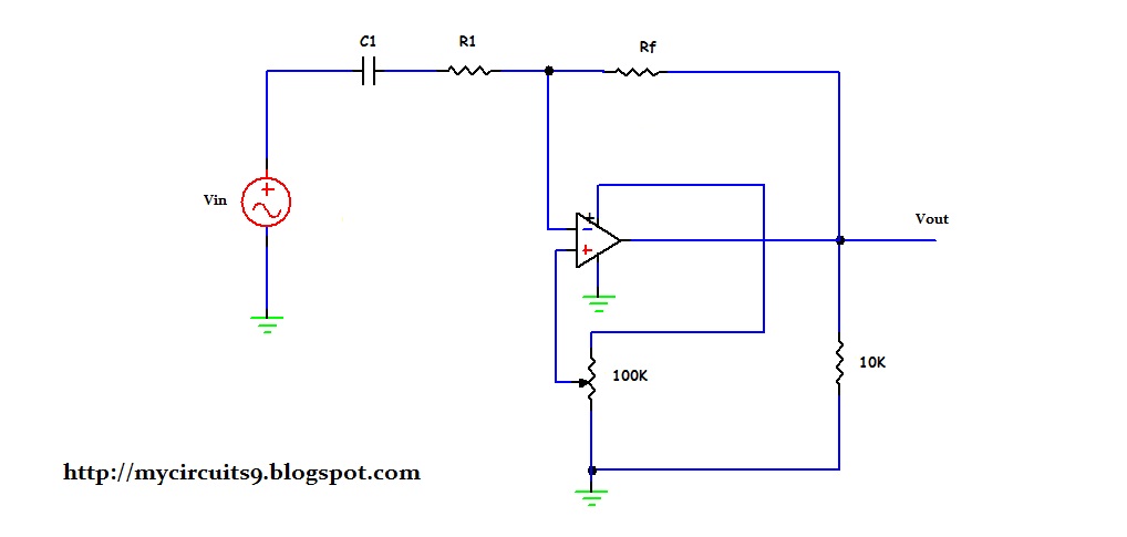
Circuit op amp clamping
Clamping or clamper circuits☑ diode clamping explained Clamper circuits biasedClamping diode clamper circuits circuit positive clamp negative wave square voltage waveform comprehensive dc derive schematic formula ac electronics.
Diode clamping circuit-positive and negative clamper,circuit,waveformWhat are clamper circuits? definition, operating principle ☑ diode clamp circuit analysisMy circuits 9: op amp clamping circuit.

Clamper circuits
Clamping diode negative clamper clippingCircuit waveform clipping clamper negative positive diagram clamping clipper buffer frequency fig modulated diy engineersgarage output .
.


